
SOLAR POWERED SMART SOLUTIONS
Easy setup guide

HOW TO
Smart device Items Needed
Solar power Items needed
Solar panel, depending on your needs. I used a 50w for just a DC light
12v Battery "I used an old car battery"
scrap wire

ESP32 PINOUT
Step One
lets build the circuit
if you used the Devices I added links to the process will go like this.
looking at your esp32 we will attach a line from the 5v Vin to the relay at the + pin
and another to the common "middle connector" on the relay. you should have Two 5v vin lines attached to the relay at opposite ends
next use the gnd pin on the esp32 and attach it to the - on the relay
next take the bulb and strip away a bit of the wire as close to the usb plug as possible. to test which line is + or - plug in the esp and touch it to the VIN and GND it will only turn on one way.
take a second GND line and attatch it to the negative line on the bulb.
next we are going to take the esp and attach a line from pin 10 counting from the Vin going up to the S pin on the relay. The pin on the esp32 is digital pin 26 or GPIO26.
we Will now attach the positive line of the bulb to the Far left port on the relay.
That's it, now if you wanted to use a different device with a alternative power source, you could just attach one leg of the device usually the Ground or negative line through the relay.


Step Two
Now we will download and setup the Blynk app.
Download the Blynk app Linked above
signup and start your first board
choose esp32 Dev board and wifi unless you want to try something different.
add one button and edit the button
The button will be assigned to Digital pin 26
The input will be 0 and output will be 1 thats your basic on off. make sure it is set to switch
next we will finish by pressing the play button

Step Three
Setting up Arduino IDE
download the Arduino IDE on your computer
select tools / manage library's
search for blynk and install
next click on tools / board: xxxxx and select board manager at the top.
search for esp32 by espressif and install that.
next we will plug in our device. using a USB cable.
once its plugged in go back to the arduino app and select File / examples / BLYNK /Boards WIFI / esp32 wifi
We will scroll down and change the Your network , and your password sections to your wireless network name and the password you use to connect to it. keeping the " "
We will need to change the authentication ID as well. open up your BLYNK app and hit the NUT icon and send your ID through email. use that ID in the authentication ID of your sketch.
Now that we Programmed the device we will upload it to our ESP32. open Tools / Board: and select esp32 DEV Module
You will want to change the Upload speed to 115200 and the frequency to 40Mhz
Now click upload and you're good to go you now have a working smart device connected to your app.

Step Four
Adding your now working device to a hub or anything else through IFTTT
Sign into IFTTT and create a new applet
For "THIS" I made a simulated switch through the smartthings ide. you could use anything whether its a clock or what ever you have.
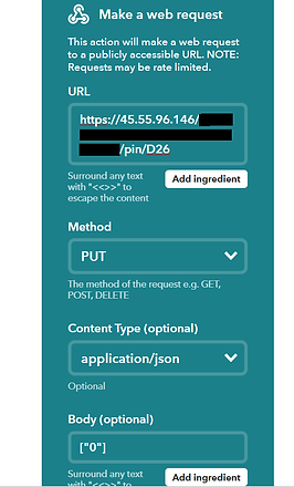
For that, search for webhooks
enter the URL for US I use there US server IP. https://45.55.96.146/ your authentication ID From BLYNK/pin/D26
then select put for method and appliction/json for the next box
In the Body section you will want to type one of two things ["0"] if you want the device to turn off or ["1"] if you want the device to turn on.
That's it, you now have a working WiFi enabled smart device

SOLAR PANEL SETUP
This is simple so I'm not going to spend to much time going over it.
place your solar panels where you want them.
attach the positive lead to the + on the charge controller
attach the negative lead to the - on the charge controller
Note: the charge controller has a picture of a solar panel indicating where the leads need to go same for the battery leads. It will have a battery icon.
now attach the positive battery lead to the quick connect and to the + on the charge controller under the battery picture.
as well do the same to the negative lead for the battery. attach it to the quick connect and then to the battery. on the charge controller attach it to the - icon.
Finally plug in your new smart device to the USB port on the charge controller via a micro USB cable.

The Techy Juan
platform Jumper VR level overview

platform Jumper VR Easter egg

level 7 preview